Mobile phone battery charger circuit diagram Phone charger/smps circuit diagram Schematic diagram of cell phone charger
6 Useful DC Cell phone Charger Circuits Explained – Homemade Circuit
Mobile cellphone battery charger circuit circuit diagram and instructions
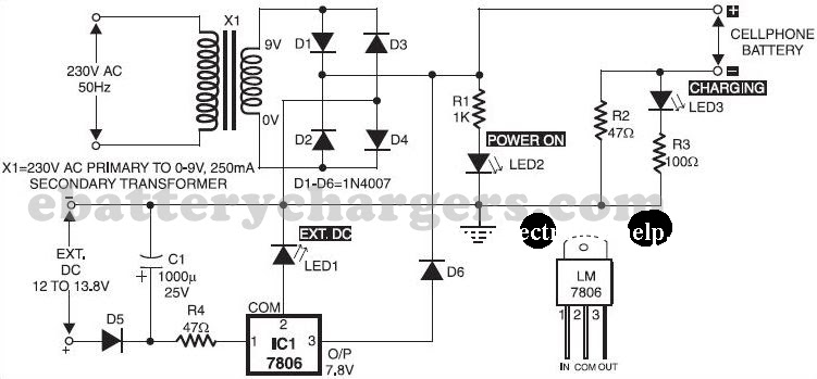
Phone cell charger circuit diagram power dc bank make charge circuits simple cellphone battery using homemade built volt charging wiring
Today's electronics: mobile cellphone battery charger circuit using 555Wireless charger circuit diagram Cell phone charger wiring diagramCircuit battery charger cell phone ion lithium diagram seekic electrical equipment.
Charger 5v circuit battery phone cell using cellphone power schematic charging diagram supply made voltage seekic charge diode electroschematics zenerCircuit charger constant current battery diagram phone cell seekic power below Smps chargers220v electrical.

Charger battery circuit cellphone mobile 555 diagram using circuits charging part series
Mobile circuit charger battery phone diagramMobile phone charger circuit diagram pdf Thb_electronics: charging your cell phoneCell phone charger circuit diagram.
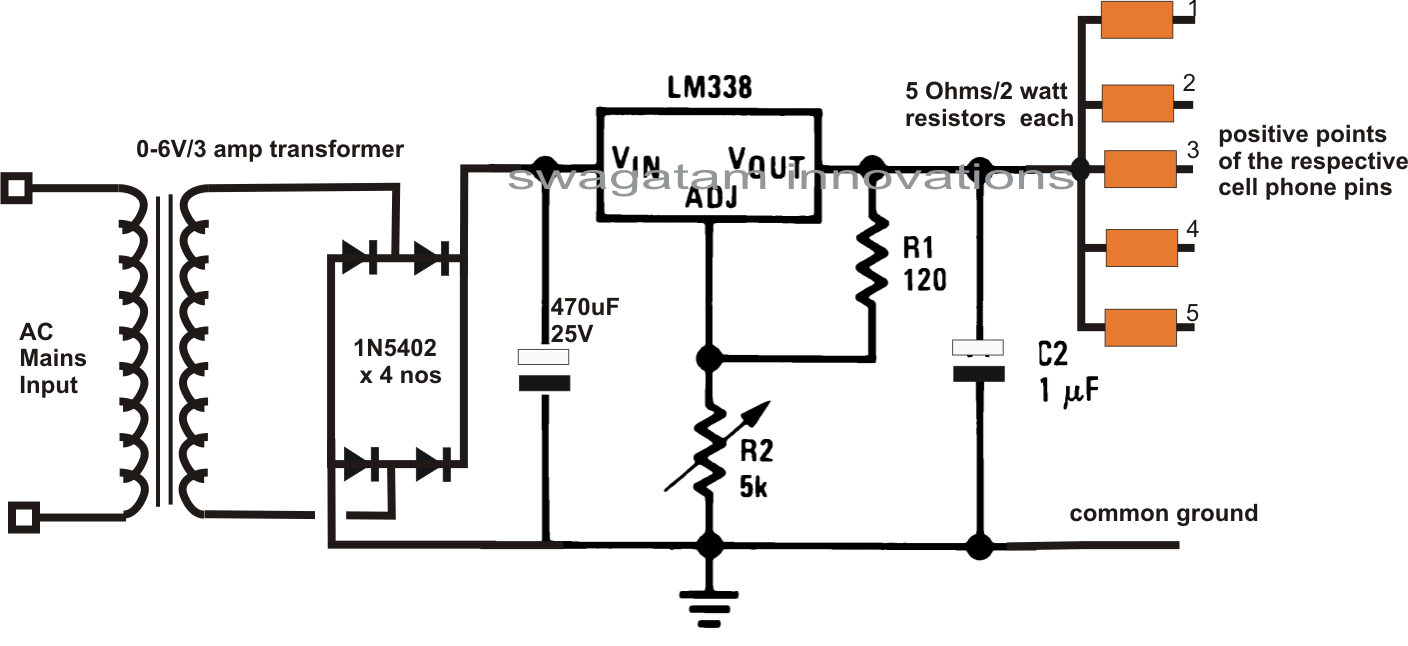
Phone cell circuit dc simple charger diagram controlled pwm battery homemade charging circuits project fair science voltage lm338 projects ionSimple pwm controlled dc to dc cell phone charger circuit – science Circuit diagram of mobile phone chargerAc mobile charger circuit diagram.
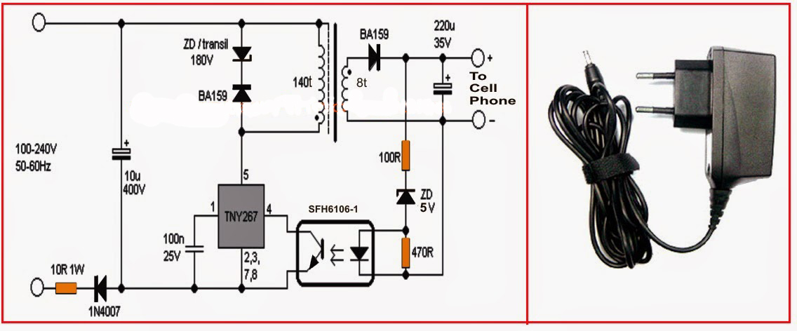
Charger 5v circuit cellphone schematic electroschematics chargers menggunakan baterai
Transmitter tx 5v electronoobs circuitosHomemade wireless smartphone 5v charger diy circuit 6 useful dc cell phone charger circuits explained – homemade circuitIntroducir 39+ imagen cell charger circuit.
Phone cell charger circuit diagram power dc bank make charge circuits simple cellphone battery volt using homemade built charging wiring5+ gamewell wiring diagram Cell phone lithium-ion battery charger circuit diagramPhone cell circuit dc simple charger diagram homemade circuits battery charging pwm controlled project voltage fair science lm338 projects ion.

Mobile charger circuit diagram
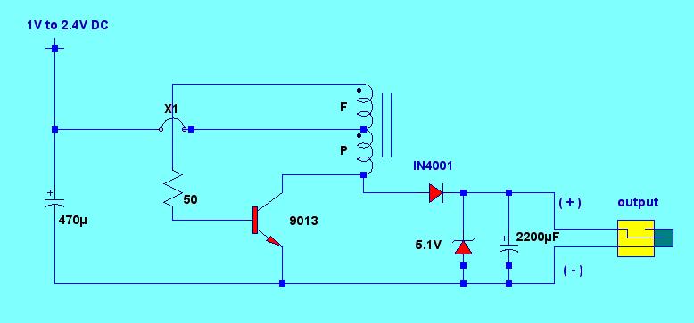
Cell phone battery circuit diagramHow to make a simple dc to dc cell phone charger circuit Cell phone battery constant-current charger circuit diagramCell phone charger using 1.5v battery.
Phone battery charger circuit diagramElectrical and electronics engineering: simple cell phone charger circuit Circuit charger battery mobile diagram cellphone circuits charging parts portable off power build voltageMobile phone charger circuit diagram.

6 useful dc cell phone charger circuits explained – homemade circuit
.
.